
Magnetic Stripe Card Reader Writer MSR605X
MSR605X is a Magnetic Stripe Card Reader Writer (Encoder) to offer a card reading/writing solution for ISO 7811-6 formats without AC power adaptor, it’s power and communication with USB interface directly. MSR605X encodes and reads ISO, AAMVA, User custom and Raw-Data card formats. It writes (encodes data), reads the data, and then verifies the encoding for up to three tracks in a single card swipe.
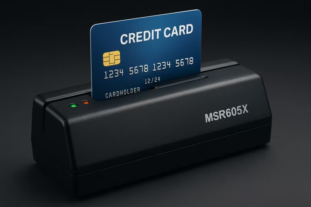
MSR605X writes/reads both High-coercivity and Low-coercivity cards. It provides a High-Speed USB interface to communicate with windows or Mac OS computers. It’s not need for extra power adapter, Works with all the major operating systems as Windows 7, 8, 10, 11 (32 & 64 bits) and Apple Computers (MacBook Air, MacBook Pro, Mac Mini, Mac Pro, iMac).
The operation and design are unique. The ABS housing and the deep card slot wiht low head force design ensures smooth and easy card swipes. Durable hard plastic casing and metal pad for sliding card keep this machine form wear and tear from extended use all of them provide stability, reliability and the accuracy required for ISO/IEC 7811 standards in the card writing process.
MSR605X comes with Free Windows and Mac software application that makes the reading and writing process quick, easy and verifiable. It’s one of the high reliable 3 tracks Hi-co magnetic card reader/writer available in the market today for small and medium size businesses which require magnetic stripe card customizations. It is ideal for access control, time keeping, banking ID recognition & credit verification and related applications. In fact, wheter a magnetic stripe ID or transaction card is used, one can find a related use for the versatile, user-friendly MSR605X magnetic.
Magnetic Stripe Card Reader/Writer (High & Low Coercivity)
MSR605X Manual Swipe Magnetic Card Reader/Writer. It is ideal for access control time keeping, banking, ID recognition & credit verification and related applications. In fact, wherever a magnetic stripe ID or transaction card is used, one can find a related use for the versatile, user-friendly MSR605X reader/writer.
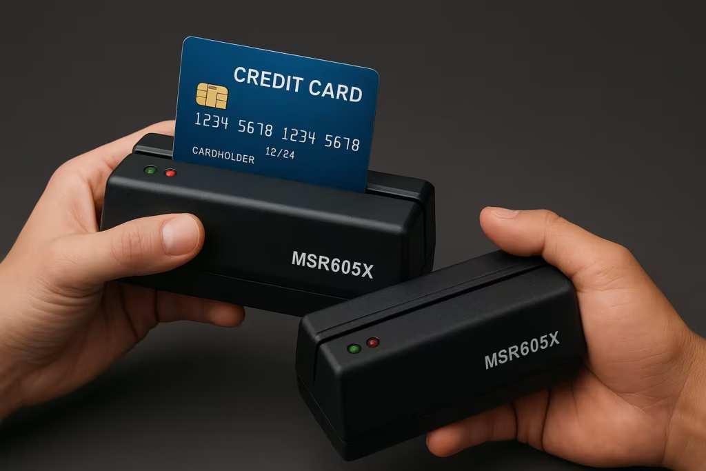
The MSR605X is designed to offer a reading and writing solution of high and/or low coercivity cards that will attractively complement an existing system.
The MSR605X series is designed to read and/or write high or low coercivity magnetic card. It can encode and verify up to 3 tracks of data simultaneously. It communicates with a host computer or other terminal using a usb interace.
Accessories of MSR605X
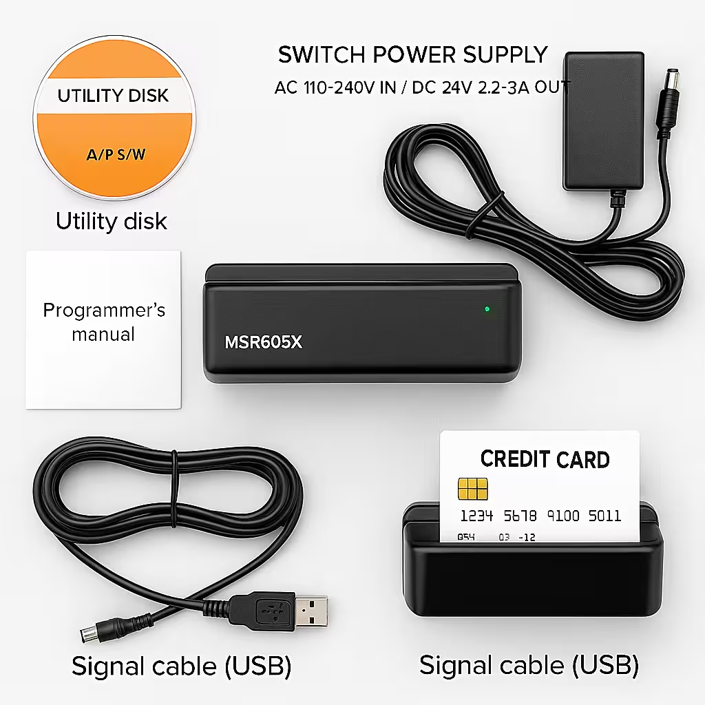
- Switch power Supply, AC 110-240V in / DC 24V 2.2-3A out.
- Power card
- Signal cable (USB)
- Utility disk (A/P S/W)
- Programmer’s manual
Features
- Meets all ISO/IEC 7811 standards for card data encoding:
- Reads and writes magnetic stripe media including cards, tickets, badges and passbooks.
- Not need external power adapter and not need USB driver, plug and play.
- Manual Swipe to read and or write card with USB output.
- Writing and verifying data on single, dual or triple track in one swipe.
- Programmable leading bit, raw data, DMV/AAMVA and user defined format; Hi or Low coercivity is easily configured by clicking a single software button. Writes any track combinations of 210 and / or 75 bpi data density.
- Can write characters at variable bit lengths.
- Operating life exceeds 1,000,000 card swipes.
- ABS housing for stability & operating life.
- EasyMSR software is easy, it guides the user through set-up of standard and custom writing & reading processes.
- LED provides operational status.
- Works with Windows XP/ Vista/ Win7/ Win8/ Win10/ Win11/ MacOS.
- CE, FCC, ROHS certified.
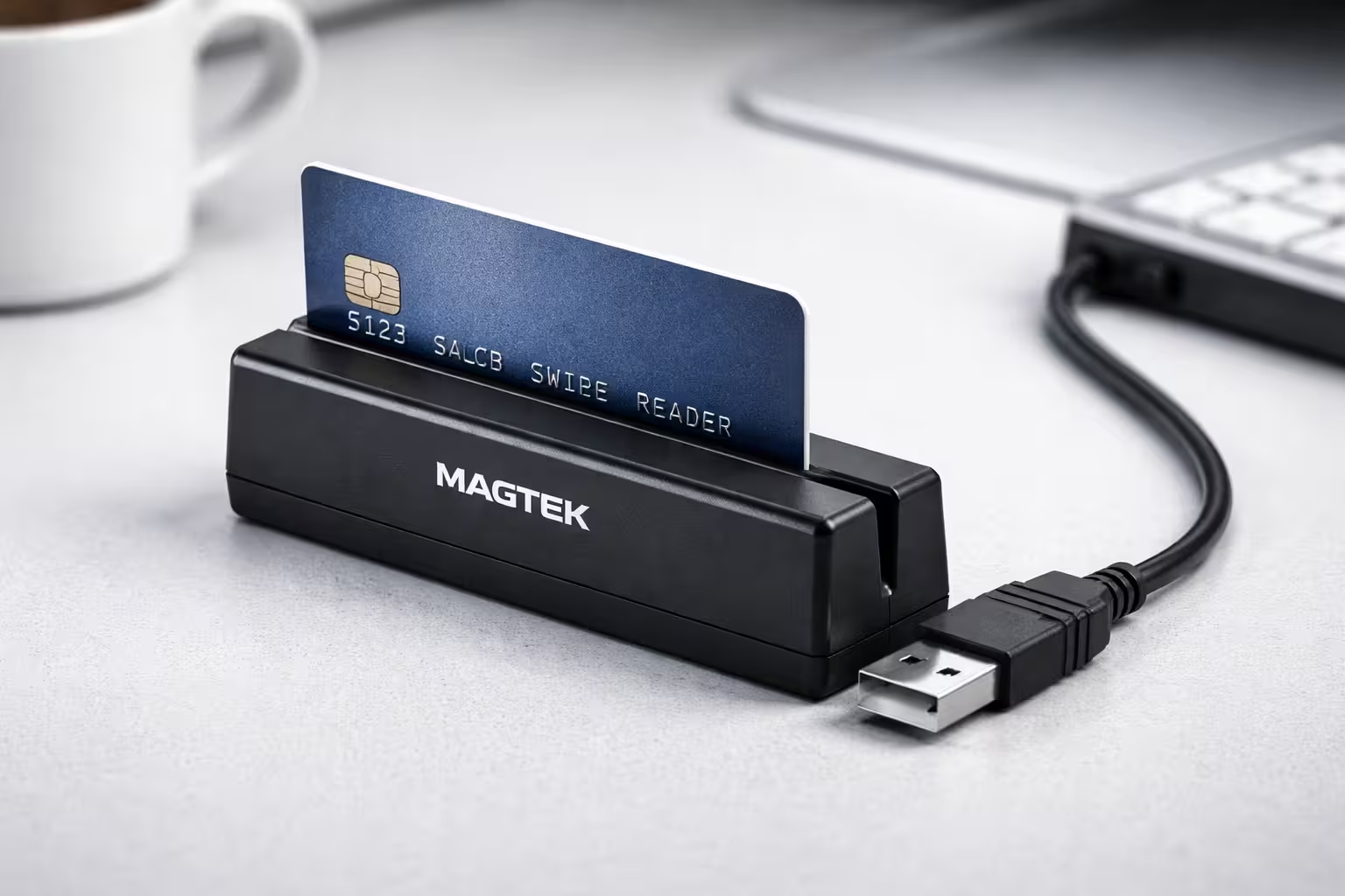
Continue Reading MagTek Mini USB Swipe Reader: A Compact and Reliable Magnetic Card Reading Solution
Continue Reading ZCS700 High-End Encoder: A Powerful Solution for Modern Card Encoding Needs
Continue Reading ZCS500 Smart Card Reader/Writer: A Reliable Solution for Modern Card Management

Specifications
| Parameter | Track 1 | Track 2 | Track 3 |
|---|---|---|---|
| Bit Density (bpi) | 75 / 210 bpi | 75 / 210 bpi | 75 / 210 bpi |
| Read Speed (ips) | 5–55 ips | 5–50 ips | 5–50 ips |
| Jitter | ±15% | ±15% | ±15% |
| Write Speed (ips) | 5–30 ips | 5–30 ips | 5–30 ips |
| Write Jitter | Interval < ±10%Sub-interval < ±12% | Interval < ±10%Sub-interval < ±12% | Interval < ±10%Sub-interval < ±12% |
| Error Rate (Read/Write) | Read < 0.5%Write < 0.8% | Read < 0.5%Write < 0.8% | Read < 0.5%Write < 0.8% |
General Specifications
| Specification | Details |
|---|---|
| Coercive Force (Read/Write) | 300–4000 Oe |
| Card Type | Magnetic Stripe Card |
| Card Thickness | 0.76–1.2 mm |
| Head Life | Minimum 1,000,000 swipes (read/write head) |
| Dimensions (L × W × H) | 8.3 × 2.5 × 2.5 inches |
| Color | Black |
| Interface | USB (HID) |
| Compatibility | Windows, Mac |
Technical Specifications
| Item | SPECIFICATION | |||
| Standard | ISO7811 | |||
| Electrical | ||||
| Consumption | Current/operating Typical 350mA Max | |||
| 600mA plus for each writing track | ||||
| Communication | Standard RS232 signal voltage levels, Default, 9600 Baud, None Parity, 8 bits | |||
| Power supply | External switching Power 24V/2.2 regulated | |||
| Interconnection | ||||
| Cable | USB | |||
| Pin Assignment USB | 1 VBUS | |||
| 2 D- | ||||
| 3 D+ | ||||
| 4 GND | ||||
| Mechanical | ||||
| Body | ABS 94V-0 / Metal housing optional | |||
| Swipe | Manual, signal direction | |||
| Outline | 212Lx64Wx63H mm | |||
| Weight | 1.4Kg approx. | |||
| Environment | ||||
| Operation | -10०C to 60०C | |||
| 10 to 85% humidity, non-condensing | ||||
| Storage | -30०C to 70०C | |||
| 10 to 90% humidity, non-condensing | ||||
| Performance | ||||
| Read Circuit | Track 1 & 3 210bpi | |||
| Track 2, 75 or 210 bpi | ||||
| Bit per Char | 5-7 bit per char. | |||
| Media Speed | Read, 5-50 ips (read speed 5-40 ips for track 2 at 210bpi) | |||
| Write 5-30 | ||||
| Media Coercivity | Read 300-4000 Oe Mag. Card | |||
| Write 300-4000 Oe Mag. Card | ||||
| Media Thickness | 0.76-1.2mm | |||
| Jitter Card | Read bit to bit interval <+/-10%, Sub interval <+/-12% at 30ips | |||
| Low amplitude Card | Read 60% for both 75 & 210bpi | |||
| Error Rate | Read < 0.5% | |||
| Write < 0.8% | ||||
| Media Swipe | Head life 1,000,000 passes for both read & write head | |||
| Configuration Available Model | Model | Read/Write Track | Hi-Co | Lo-Co |
| MSR605X | 1,2&3 | R/W | R/W | |
How to Setup MSR605X on your Windows?
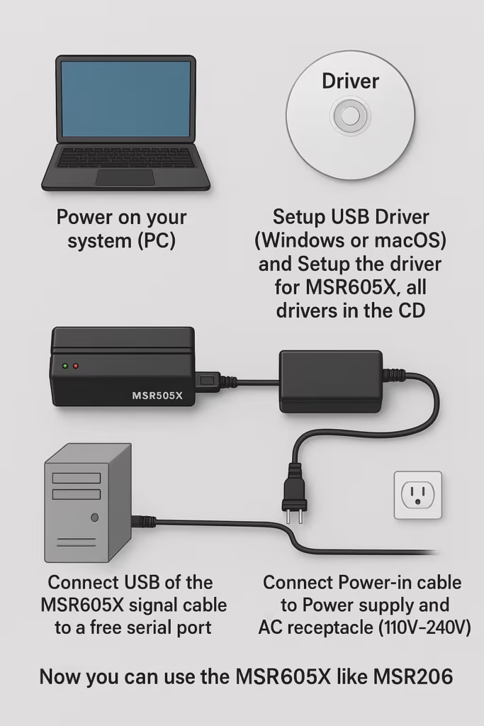
- Power on your system (PC).
- Setup the usb driver (for windows or macOS) and Setup the driver for MSR605X, all driver in the cd.
- Connect USB of the MSR605X signal cable to a free serial port.
- Connect Power-in cable to Power supply and AC receptacle (110V~240V).
- Now you can use the MSR605X like MSR206.
Utilities Test Program
Every MSR605X comes with a utilities test program disk that inlcudes a Windows version. This program is to verify and demonstrate the functionality of the MSR605X. In some cases, it can be used as a card reading and writing program.
System Requirement
- 80286 PC/AT compatible or later model with color display.
- Either the following operating systems: Windows 7,8,10,11
- 256K available conventional memory.
- A free serial port (Com 1 or Com 2) with DB9 male connector.
Test Program Installation
- User shall follows the steps below in order to install test program.
- Connect MSR605X to USB port, and power on it.
- Execute test program from the subdirectory of “Demo AP” (e.g. MSR605.exe)
- When the test program is first opened, a password dialog box will ask whether you wish a first time password.
- The test program will auto-detect communication port. If there is any errors occurred, it’ll appear in the information dialog box after opening the program. User can close the AP by pressing OK button.
- If “Not Find Reader/Writer!” appears in the information dialog box after opening the program, check to see that the USB connector is plugged into the correct USB port and the power cord/connector is also attached to USB thus lighting the gree LED on the MSR605X.
- When the test program is opened, you’ll see the main window of the READER/WRITER UTILITY PROGRAM.
Frm this main window you can activate all functions by clicking the appropriate buttons and following the on screen instructions.
Command and Response
This section gives detailed description of commands to the MSR605 and the corresponding responses from MSR605X.
National Conventions:
| <ESC> | Control character named |
| [[[[ [sname] | Special string named sname, meaning can be found in section 7. ie. [Data Block] [Status Byte] [Select Byte] etc. |
| X | Standard ANSI character |
Command Description
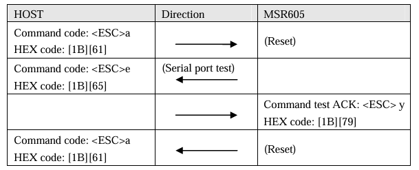
- Command: RESET
Command code: <ESC>a
Hex code: 1B 61
Response: none
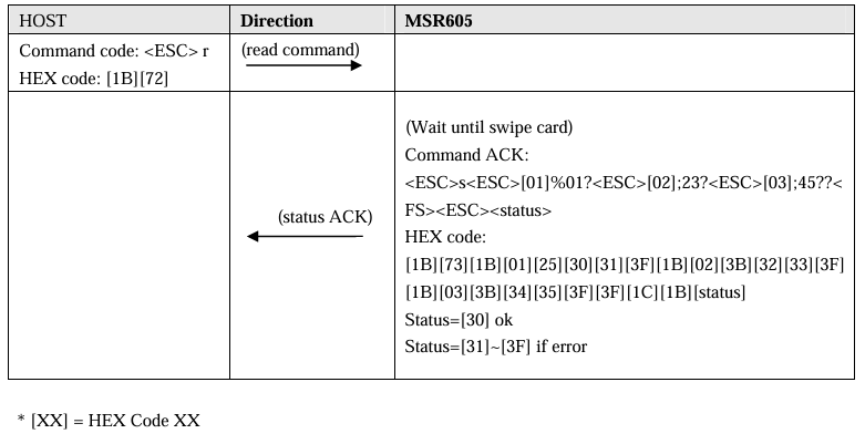
Description: This command reset the MSR605X to initial state. - Command: READ (ISO format only)
Command code: <ESC>r
Response: [Data Block] <ESC> [Satus Byte]
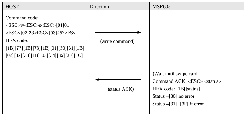
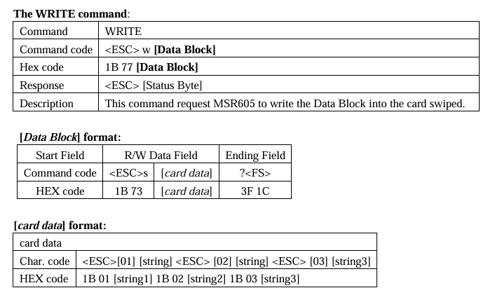
Description: This command request MSR605 to read a card swiped and responsed with the data read. - Command: Write (ISO format only)
Command code: <ESC>w.[Data Block]
Hex code: 1B77 [ Data Block]
Response: <ESC> [Status Byte]
Description: This command request MSR605X to write the Data Block into the card swiped. - Command: Communication test
Command code: <ESC>e
Hex code: 1B 65
Response: <ESC>y[1B][79]
Description: This command is used to verify that the communication link between computer and MSR605X is up and good. - Command: All LED off
Command Code: <ESC><81>
Hex code: 1B 81
Response: none
Description: This command is used to turn off all the LEDs. - Command: All LED on
Command code: <ESC><82>
Hex code: 1B 82
Response: none
Description: This command is used to turn on all the LEDs. - Command: GREEN LED on
Command code: <ESC><83>
Hex code: 1B 83
Response: none
Description: This command is used to turn on the Green LED. - Command: YELLOW LED on
Command code: <ESC><84>
Hex code: 1B 84
Response: none
Description: This command is used to turn on the Yellow LED. - Command: RED LED on
Command code: <ESC><85>
Hex code: 1B 85
Response: none
Description: This command is used to turn on the Red LED. - Command: Sensor test
Command code: <ESC><86>
Hex code: 1B 86
Response: <ESC>0 (1B 30) if test ok
Description: This command is used to verify that the card sensing circuit of MSR605X is working properly. MSR605X will not response until a card is sensed or receive a RESET command. - Command: Ram test
Command code: <ESC><87>
Hex code: 1B 87
Response: <ESC>0 (1B 30) ram test ok; <ESC> A (1B 41) ram test fail
Description: This command is used to request MSR605X to perform a test on its on board RAM. - Command: Set leading zero
Command code: <ESC>z [laeading zero of track 1 & 3] [leading zero of track 2]
Hex code: 1B 7A [00-ff] [00-ff]
Response: <ESC
Description: This command is used to set how many leading zeros will be written before the card the space should calculated as [leading zero] X25.4 / BPI (75or210) = mm
Default setting of leading zero: [3d] [16]
TK1 & TK3: [3D] means leading zero = 61
TK2: [16] means leading zero=22 - Command: Check leading zero
Command code: <ESC>1
Hex code: 1B 6C
Response: 1B [00-ff] [00-ff]
Description: This command is used to ask MSR605 the present setting number of leading zeros. - Command: Erase card
Command code: <ESC>c [ Select Byte]
Hex code: 1B 63 [ Select Byte]
Response: <ESC>0 [1b] [30] command Select Byte ok
<ESC>A [1b][41] command Select Byte fail
Description: This command is used to erase the card data when card swipe.
*[Select Byte] format:
00000000: Track 1 only
00000010: Track 2 only
00000100: Track 3 only
00000011: Track 1 & 2
00000101: Track 1 & 3
00000110: Track 2 & 3
00000111: Track 1, 2 & 3 - Command: Select BPI
Command code: <ESC>b [Density]
Hex code:
track2: 1B 62 [D2 or 4B] // [D2]: 210bpi, [4B]: 75bpi
track1: 1B 62 [A1 or A0] // [A1]: 210bpi, [A0]: 75bpi
track3: 1B 62 [C1 or C0] // [C1]: 210bpi, [C0]: 75bpi
Response:
<ESC> 0 [1B] [30] select ok
<ESC> A [1B] [41] select fail
Description: This command is used to select the density - Command: Read raw data
Command code: <ESC> m
Hex code: 1B 6D
Response: [Raw Data Block] <ESC> [Status Byte]
Description: This command requests MSR605X to read a card swipe but send without ASCII decode. Refer to [Raw Data Block] & [Raw Data] format. - Command: Write raw data
Command code: <ESC>n [Raw Data Block]
Hex code: 1B 6E [Raw Data Block]
Response: <ESC> [Status Byte]
Description: This command requests MSR605X to write raw Data Block into the card swiped. Refer to [Raw Data Block] & [Raw Data] format. - Command: Get device model
Command code: <ESC> t
Hex code: 1B 74
Response: <ESC> [Model] S
Description: This command is used to get the model of MSR605. - Command: Get firmware version
Command code: <ESC> v
Hex code: <ESC> 76
Response: <ESC> [version]
Description: This command can get firmware version of MSR605X. - Command: Set BPC
Command code: <ESC> o [tk1bit][tk2bit][tk3bit]
Hex code: <ESC> 6F [05-08][05-08][05-08]
Response: <ESC> 30 [tk1bit][tk2bit][tk3bit]
Description: This command is used to set the bit per character of every track. - Command: Set Hi-Co
Command code: <ESC> x
Hex code: 1B 78
Response: <ESC>0
Description: This command is used to set MSR605 status to write Hi-Co card. - Command: Set Low-Co
Command code: <ESC>y
Hex code: 1B 79
Response: <ESC> 0
Description: This command is used to set MSR605X status to write Low-Co card. - Command: Get Hi-Co or Low-Co Status
Command code: <ESC> d
Hex code: 1B 64
Response:
<ESC> H——to write Hi-Co
<ESC> L——-to write Low-Co
Description: This command is to get MSR605X write status.
Data Format
*[Data Block] format:
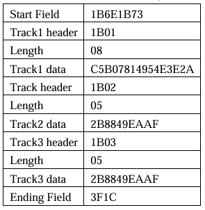
| Start Field | R/W Data Field | Ending Field | |
| Command code | <ESC> s | [Card data] | ? <FS> <ESC> [Status] |
| Hex code | 1B 73 | [Card data] | 3F 1C 1B [Status] |
*[Card data] format:
| Card Data | |
| Char Code | <ESC>1 [string1] <ESC>2 [string2] <ESC>3 [string] |
| Hex Code | 1B 01 [string1] 1B 02 [string2] 1B 03 [string3] |
*[Status Byte] format:
| Status | Description | HEX | ASCII |
| Ok | If read, write or command ok | 30h | 0 |
| Error | Write or read error | 31h | 1 |
| Command format error | 32h | 2 | |
| Invalid command | 34h | 4 | |
| Invalid card swipe when in write mode | 39h | 9 |
*Note:
- When [Status Byte] equal 39h means card moving error.
- None available and none data tracks will not be transmitted when swipe of card.
For example, when read card with data encoded on track 2 only for MSR605, it will transmit data like 1B 73 1B 01 1B 02 [string] 3F 1C for no data on track 1 so it shown 1B 01 only.
*[Raw Data Block] format:
| Start Field | R/W Data Field | Ending Field | |
| Command code | <ESC>s | [Raw data] | ?<FS><ESC>[Status] |
| Hex code | 1B 73 | [Raw data] | 3F 1C 1B [Status] |
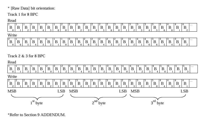
*[Raw Data] format:
| Raw Data | |
| Char Code | <ESC>1[l1][string1]<ESC>2[L2][string2]<ESC>3[L3][string3] |
| Hex Code | 1B 01[L1][string1]1B 02[L2][string2]1B 03[l3][string3] |
Note:
- [L1],[L2],[L3] is the length of [string1],[string2] and [string3]
- None available and none data tracks will not output when swipe of card.
For example, when read card (encoded data on track 2 only) on MSR605X, it will transmit data like 1B 73 1B 01 00 1B 02 [L2] [string] 3F 1C.
Communication Sequence
The examples below assumes data on track 1, 2 & 3 to be 01, 23, 45 respectively.
- MSR605X INITIALIZATION
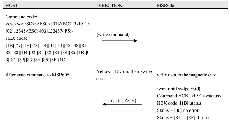
- Write Data to MSR605X
- Read Data to MSR605X
Addendum
- Write Data to Magnetic Card
As an example the following information will be written to the card:
Track1: %ABC123?
Track2: ;12345?
Track3: ;12345?
Write Raw Data to Magnetic Card
Converting Card Data Information to Hexadecimal for the Binary Write Function Converting track one ASCII information into HEX.
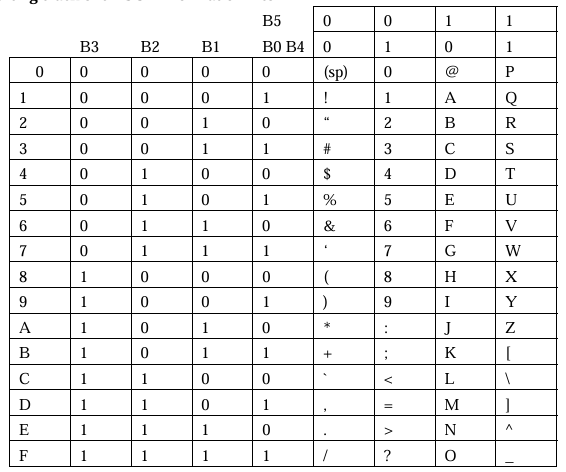
Converting track two and three ASCII information into HEX
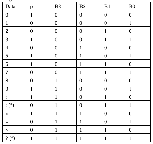
*Note: The “;” is start sentinel and “?” is end sentinel of tk2 & 3 of ISO format.
As an example the following information will be written to the card:
Track1: %ABC123?
Track2: ;12345?
Track3: ;12345?
We use three different data bits to write raw data on the cards. The procedures are listed as below:
08, 08, 08 BITS
Set each track as 08.
First of all, set BPC command:
1B, 6F, 08, 08, 08
Present the information to the card encoder, as follows:
Transfer the track 1 data to HEX under 08 bits:
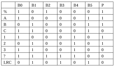
Calculate Odd Parity (P column)
If there is an Even Number of 1’s in the row of data for each character, put a 1 in the P column. Other wise, put a 0 in the column.
LRC: If there is an Even Number of 1’s in the column of data for each chracter, put a 0 in the LRC row. Other wise, put a 0 in the row. The last LRC will be considered as the parity rule of this row.
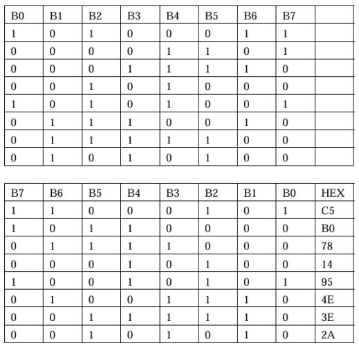
Transfer track 2 (track 3) data to HEX under 08 bits:
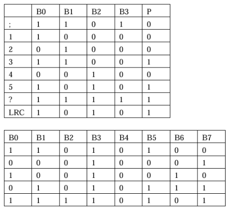
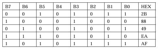
07, 05, 08 BITS
Set TK1, TK2 & TK3 as 07, 05, 05
1B, 6F, 07, 05, 05
First of all, set BPI command:
Present the information to the card encoder, as follows:
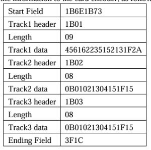
Transfer the track 1 data to HEX under 07 bits:
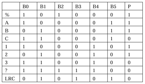
Calculate Odd Parity (P column)
If there is an Even Number of 1’s in the row of data for each character, put a 1 in the P column. Other wise, put a 0 in the column.
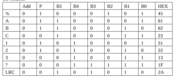
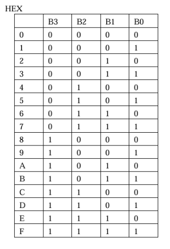
Transfer track 2 (track 3) data to HEX under 05 bits:
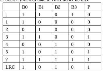
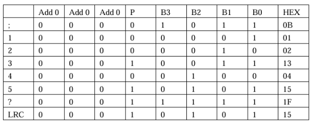
Set TK1, TK2 & TK3 as 06, 05, 06
First of all, set BPI command:
1b, 6F, 06, 05, 06
Present the information to the card encoder, as follows:
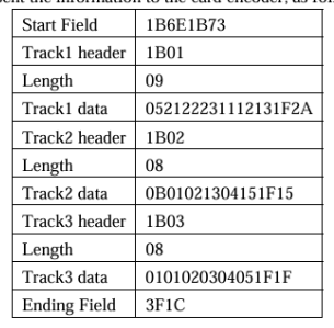
Transfer track1 data to HEX under 06 bits:
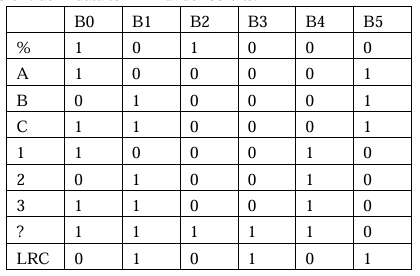
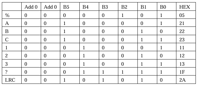
Transfer track 2 data to HEX under 05 bits:
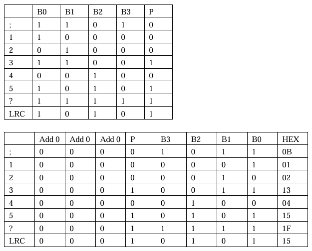
Transfer track 3 data to HEX under 06 bits:
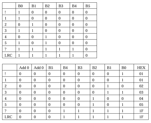
Application
- Financial Banking: Credit Card, Debit Card, Bank Card
- Retail: Gift Card, Customer ID, Store ID
- Government: Driver Licence, Health Card, Government ID
- Movable Data Collection: Trade shows, Racing events
- Employee Time/Attendance Data Collection
- Exhibition Visitors’ Data Collection
- Conference Attendants Data Collection
- Card Verification: Age Verification
- Point of Sales: Payment Collection, Credit Card Data Collection
- Law Enforcement: DMV Card
- Attendance: Student ID, Membership Card, Club ID